Su Suntan History of the Capacitor
March 10, 2009 Views
Comments 0
When using a capacitor, you must pay attention to the maximum voltage which can be used. This is the "breakdown voltage." The breakdown voltage depends on the kind of capacitor being used. You must be especially careful with electrolytic capacitors because the breakdown voltage is comparatively low. The breakdown voltage of electrolytic capacitors is displayed as Working Voltage.
The breakdown voltage is the voltage that when exceeded will cause the dielectric (insulator) inside the capacitor to break down and conduct. When this happens, the failure can be catastrophic.
Suntan Technology Company Limited
---All kinds of Capacitors
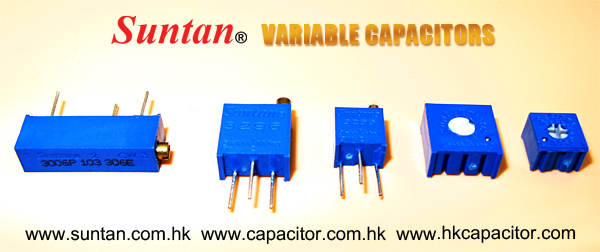
Variable capacitors are mostly used in radio tuning circuits and they are sometimes called 'tuning capacitors'. They have very small capacitance values, typically between 100pF and 500pF (100pF = 0.0001µF). The type illustrated usually has trimmers built in (for making small adjustments - see below) as well as the main variable capacitor.
Many variable capacitors have very short spindles which are not suitable for the standard knobs used for variable resistors and rotary switches. It would be wise to check that a suitable knob is available before ordering a variable capacitor.
Variable capacitors are not normally used in timing circuits because their capacitance is too small to be practical and the range of values available is very limited. Instead timing circuits use a fixed capacitor and a variable resistor if it is necessary to vary the time period.
Storage—there is never enough of it. I still remember when I thought my 700MB hard drive was huge... until I tried to copy an entire CD onto it for faster access. After that, I spent a period stuck choosing music to stick on my three GB hard drive. Two weeks ago, I ditched six months' worth of simulation data because my 320GB hard drive was full. One TB of new drive later, and I'm wondering how soon it will be before I start feeling the squeeze again. Maybe never, if some of the latest research coming out of Korea and Germany bears fruit.
One of the cool things about hard drive technology is how it has actually kept pace with computer needs. The basic mechanism for hard drive storage, however, does have some fundamental limitations, which manufacturers will have to deal with fairly soon. Bits are currently stored in the orientation of tiny magnets, called ferromagnetic domains, on a hard drive platter. The smaller the domain, the easier it is for that orientation to be scrambled by temperature or stray electromagnetic fields. At a certain size, thermal photons (e.g., heat energy from the surrounding case or the underlying disk) have enough energy to flip a domain's orientation. Manufacturers will have to keep their domain sizes significantly bigger than that threshold size to ensure data integrity, which puts a ceiling on storage density, one we're rapidly approaching.
An alternative is to use ferroelectric domains. Unlike ferromagnetic domains, ferroelectric domains have a natural electric field with an orientation that can be used to represent data. Until recently, these haven't looked that attractive because they have pretty much the same limitations that ferromagnetic domains have, but they lack the cool read-out tricks. Ferroelectric materials, however, do have one big advantage over ferromagnetic materials: they can be used to make really good capacitors. This is exactly what the latest research, published in Nature Nanotechnology, is about.
Suntan Technology Company Limited
---All kinds of Capacitors
I worked as a design engineer for an optical-telecom company that had deployed 1000 pieces of equipment worldwide. Having so many modules in the field means a trickle of returns, and it was my job to investigate the failures. One investigation taught me a wonderful lesson.
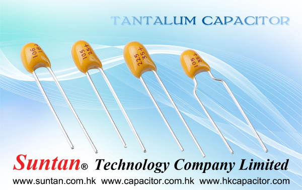
I received a module whose source of failure was easily identifiable: a charred tantalum capacitor. It failed short, making the whole multithousand-dollar module nonoperational. This surface-mount capacitor—with a 7343 footprint and 20V rating—was sitting on a 12V-dc plane. This failure rate of one capacitor in about 10,000 pieces in this time span was well below the statistical prediction. I took a picture of the fallen capacitor and considered the case closed.
In a few weeks, a customer returned a similar module with a charred and shorted capacitor in the same location. Even including this case, the failure rate was still below statistical prediction. I knew there were five more identical capacitors on the board, sitting in parallel on the same 12V-dc plane. In addition to the module's failure rate, I now had a one-in-six chance with the capacitors. So, I took another picture. I wrote a report to calm upper management, but I had a feeling that I'd better study reliability calculation in general and reliability for tantalum capacitors in particular, and the faster, the better.
In another few weeks, I received another failed module. The same capacitor looked bad. I had by now done my studying and could intimidate other people by saying long and complicated sentences about reliability, but why was it always the same capacitor? Overvoltage? Spikes? No way. The same plane contained plenty of sensitive stuff that would fry well before the capacitor even felt it. Having nothing better, I clung to the theory of excessive ripple current.
The idea of a temperature rise due to ripple current causing the failure gained traction when all three photos of the fallen capacitors revealed a common condition: almost no solder on each negative terminal. The electrical connection was still good, but there was little solder. The capacitor's positive terminal was fine with a fair amount of curvature-profiled solder. I started to promote the idea that the lack of solder had caused impeded thermal contact, but it was only wishful thinking. I calculated the worst ripple current: 10% of the maximum rating. On an operational board, I got less than 5%.
I had already dismissed other ideas—from excessive humidity to airflow turbulence. Suddenly, the picture of the layout popped up in my mind. The layout sections for the five good capacitors were identical: Vias were close to both terminals going down to an internal layer. The bad capacitor had a via at the positive terminal, but, at the negative end, there was a heavy trace going inside the footprint, beneath the capacitor, and only then outside. That's when I knew how to fit together all the pieces of the puzzle.
On the positive terminal, the solder stayed where it was supposed to, clinching the terminal to the PCB (printed-circuit board). On the negative side, however, during assembly, the melted solder drifted under the capacitor and solidified, lifting the negative end and bending the capacitor just enough to create a microcrack—a capacitor's well-known nemesis. I never felt as much excitement writing a technical report as I did the next day.
Suntan Technology Company Limited
---All Kinds of Capacitors
In October 1745, Ewald Georg von Kleist of Pomerania in Germany found that charge could be stored by connecting a generator by a wire to a volume of water in a hand-held glass jar. Von Kleist's hand and the water acted as conductors and the jar as a dielectric. Von Kleist found that after removing the generator, touching the wire resulted in a spark. In a letter describing the experiment, he said "I would not take a second shock for the kingdom of France." The following year, the Dutch physicist Pieter van Musschenbroek invented a similar capacitor, which was named the Leyden jar, after the University of Leyden where he worked. Daniel Gralath was the first to combine several jars in parallel into a "battery" to increase the charge storage capacity.
Benjamin Franklin investigated the Leyden jar, and proved that the charge was stored on the glass, not in the water as others had assumed Leyden jars began to be made by coating the inside and outside of jars with metal foil, leaving a space at the mouth to prevent arcing between the foils. The earliest unit of capacitance was the 'jar', equivalent to about 1 nanofarad.
Leyden jar or flat glass plate construction was used exclusively up until about 1900, when the invention of wireless (radio) created a demand for standard capacitors, and the steady move to higher frequencies required capacitors with lower inductance. A more compact construction began to be used of a flexible dielectric sheet such as oiled paper sandwiched between sheets of metal foil, rolled or folded into a small package.
Early capacitors were also known as condensers, a term that is still occasionally used today. It was coined by Alessandro Volta in 1782 (derived from the Italian condensatore), with reference to the device's ability to store a higher density of electric charge than a normal isolated conductor. Most non-English European languages still use a word derived from "condensatore".
Learn more:http://www.suntan.com.hk/

Tel: (852) 8202 8782
Fax: (852) 8208 6246
Email sales@suntan.com.hk
Website www.suntan.com.hk